
Applicable Models:
📜 Quick Navigation
Start Up Procedure
- Before proceeding, ensure that all internal and external packaging has been removed from the appliance, including tape, plastic bags, and foam pieces.
- Take the supplied lead and plug it into the male IEC socket on the rear of the incubator. Next, plug the 3-pin plug into a 10A General Purpose Outlet.
- The controller will go through a warm-up period before displaying the security screensaver (SOV mode).
- Factory Settings: Upon first start-up, the temperature will be set at 22.0°C.

Security Screen Saver
When the STAR touchscreen is powered on—or after any power cycle—the screensaver will be displayed. To proceed to the Main Screen, you must enter the correct access credentials.
Accessing the Main Screen
-
Tap the Thermoline Logo
On the screensaver display, press the Thermoline logo to bring up the User Access window.
-
Enter User Credentials
-
Tap the User Number field and enter:
01 -
Tap the Password field and enter:
1111
Then press Enter after each input.
-

Exit the User Access Screen
After entering the credentials, tap anywhere above the Thermoline logo to proceed to the Main Screen and close the User Access window.
Star X User Guide
Main Screen Overview
The TMLR-200 uses the STAR X touchscreen controller, designed for ease of use, security, and traceability. Each unit features a unique identifier displayed in red for reference and data logging.

Temperature Display
-
The temperature is fixed at 22.0°C.
-
The value shown in the top left represents the block temperature of the incubator.
Trend Chart
The main screen includes a real-time horizontal chart showing cabinet performance:
-
Red and blue lines represent high and low alarm thresholds.
-
You can observe the temperature trend over time for quick diagnostics.
Chart Controls
Using the drop-down menu, you can:
-
Adjust the Y-axis scale
-
Select a specific month to view historical data
-
These options are also available on the Trend Screen for more detailed review.


USB and Ethernet Connectivity
The TMLR-200 is equipped with:
-
A built-in USB port
-
A built-in Ethernet port
Both are conveniently located on the left side of the touchscreen control panel, enabling:
-
USB data downloads (e.g., logs and alarms)
-
LAN connection for remote screen monitoring or cloning
These features allow for seamless data management and integration with external systems.

Alarms

The STAR X is equipped with multiple alarm systems to ensure the safety and performance of the cabinet. Below is a guide to each alarm type and its function.
Power Fail
In the event of a power failure, the STAR X uses an internal battery to maintain alarm and touchscreen functionality for approximately 24 hours.
- Refer to the shutdown procedure if extended power loss occurs.
Battery Fail
Every 7 days, the controller automatically performs a battery health test.
If the voltage drops below 22VDC during the test, a battery alarm will trigger.
- The battery may need replacement if this occurs.
Door Alarm
If the cabinet door is opened, the STAR X will display a door message.
If the door remains open for over 1 minute, a Door Alarm will activate.
Shaker Alarm (TPS-18 only)
Triggers if:
-
The power is disconnected from the TPS-18, or
-
The shaker stops moving.
If powered but not moving, the alarm will activate after 1 minute.
Temperature Alarm
Triggers when the air temperature inside the cabinet:
-
Rises above 30°C, or
-
Drops below 10°C.
This is a latching alarm and requires manual acknowledgment.
Ambient Air Alarm
Triggers when the ambient air temperature exceeds 43°C or falls below 5°C.
This is a latching alarm and must be acknowledged by the operator.
Temperature Deviation Alarm (Block High/Low)
-
High Alarm:
Activates if block temperature exceeds 23.5°C.
A latching alarm — acknowledgment is only possible when the temperature returns to 21°C–23°C. -
Low Alarm:
Activates if block temperature drops below 20.5°C.
Also a latching alarm, with acknowledgment only when within the normal range.
Latching Alarms
A latching alarm stays visible even after conditions return to normal.
You must press and hold to acknowledge and clear the alarm.
If unacknowledged, it will return every 15 minutes until resolved.
NOTE:
You must be on the Main Screen to mute or acknowledge alarms. Alarms can only be acknowledged after the condition has cleared.
Service Tip:
If alarms persist, contact a qualified service technician.

USB Downloading
The STAR X controller allows easy retrieval of logged data via USB. Simply insert a USB memory stick into the port, and the system will begin automatic downloading of all available data.
⚠️ Do not remove the USB stick until the controller indicates it is safe to do so.
How It Works:
-
Insert a USB stick into the port.
-
The screen will display:
“Alarm/Event & Data Downloading – Do not Remove USB” (Red Banner) -
Once the process is complete, the message will change to:
“Safe to Remove USB” (Green Banner)

Data Format & Storage:
-
File Structure: Logged data is stored in monthly files.
-
File Naming: Format is MM/YYYY (e.g., 03/2025 for March 2025).
-
Retention Limit: Up to 12 months of data can be stored at one time.
-
Log Interval: Data is logged at 1-minute intervals.
-
File Format: CSV (Comma-Separated Values) – compatible with Excel, Google Sheets, and other spreadsheet programs.
Each file is tagged with the unit’s unique identifier, enabling full traceability.
Note: Make sure the USB Drive you are using is formatted and has no other data or files on it before downloading.
Settings Screen
From the Main Screen, you can access the full range of configuration and system functions by pressing the Settings button located in the bottom left corner of the display.

Navigating to the Settings Menu
-
Tap the Settings button (as shown with the red arrow).
-
This will open the Settings Screen, where all system features are accessible.

Access Levels
-
The top row of the Settings Screen includes basic functions that do not require a passcode.
-
The bottom row contains advanced settings that are passcode protected.
Accessing Passcode-Protected Functions
To unlock protected settings (e.g., Calibration, Program Set-Up):
-
Tap the Thermoline logo in the bottom-right corner of the screen.
-
Enter the following credentials:
-
User Number:
02 -
Passcode:
2222
-
-
After entering the passcode, press the desired menu item before closing the dialog box.
⚠️ Note: If you close the User Access window using the "X" without selecting a function, you will need to re-enter the passcode.
Contact Details Screen
If you need to contact Thermoline for any reason, our contact details are available by pressing the Contact Details Screen button on the settings page.

Trend Screen
The STAR X controller offers two types of trend displays to help monitor cabinet performance over time:
-
Graph View
-
Includes both circular and horizontal line charts
-
Ideal for visualizing temperature and system data trends
-
-
Data Table View
-
Displays historical data in a structured, timestamped format
-
Useful for analysis and exporting to external tools
-

How to Use the Trend Screen:
-
Access the Trend Screen from the Settings Menu.
-
A selection window will appear, allowing you to choose from the three available trend views.
-
Use the drop-down menu to select the desired date/month for the data you wish to review.
These tools are essential for diagnostics, performance reviews, and compliance logging.
Using the Horizontal Charts
On the horizontal trend charts, you can cycle through three display ranges by using the Next and Back buttons located at the bottom of the screen.
To select the data file (by month):
-
Tap the cogwheel icon in the top right corner of the screen.
-
Choose the desired month from the available file list.
This allows you to easily navigate and review historical performance data.


Alarm/Events Screen
The Alarm/Events Screen is accessed through the Settings Menu. This screen logs all key system events and alarm activity within the STAR X touchscreen controller.

Recorded Events Include:
-
Alarm activations and clearances
-
User logins and passcode entries
-
Access to different screens
-
Activation and deactivation of system functions
How to Read the Alarm Log:
-
Entries shown in red indicate when an alarm or event was triggered.
-
Entries in green indicate when the condition returned to normal or was acknowledged.
This feature is essential for tracking system usage, troubleshooting, and maintaining compliance with operating procedures.
System Settings Screen
NOTE: To access this screen, use:
User Number:02
Passcode:2222
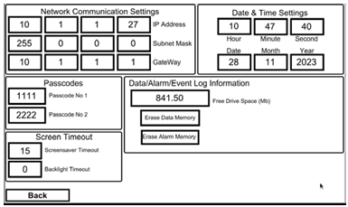
From the Settings Menu, press the Date, Time, Network & System Settings Screen button. This screen provides access to key controller configuration features.

Available Settings:
Network Settings
-
Displays the IP address once connected to a network.
-
Useful for LAN access and remote monitoring.
Time and Date Settings
-
Tap any field (hour, minute, day, etc.) to enter the desired values.
NOTE: The STAR X does not adjust for daylight savings. Changes must be made manually.
Reminder: Logged data uses the time and date shown here. If incorrect, logs will reflect the wrong timestamp.
Other Configurable Options:
Screen Timeout
-
Screensaver Timeout: 1–255 minutes
-
Backlight Timeout: 0–255 minutes
Setting to 0 disables the timeout and keeps the screen always on.
Passcodes
-
Passcode 1 (User 1): For basic access (e.g., exiting screensaver).
-
Passcode 2 (User 2): Unlocks access to Calibration, System Settings, and Program Set-Up.
IMPORTANT:
Thermoline cannot retrieve lost/forgotten passcodes.
A factory reset will be required, which will erase all logged data.
Log Information
-
Displays memory usage and remaining storage capacity.
-
Data is logged every minute and can be stored for up to 365 days.
-
File size varies based on logging activity.
Erasing Data:
To clear logged data:
-
Press and hold the Data Erase button for 10 seconds.
Prevents accidental deletion.
LAN Connection
The STAR X controller includes a built-in LAN port for remote screen cloning and monitoring.
-
When connected to an active network, the controller automatically assigns an IP address (visible in Network Settings).
-
To configure a manual IP address, contact Thermoline support.
This feature is ideal for remote management, diagnostics, and integration with centralised monitoring systems.
Calibration
NOTE: All calibration procedures should be performed by a qualified service technician.
The STAR X touchscreen includes a simple one-point calibration adjustment for maintaining temperature accuracy.

Accessing the Calibration Screen
Access to the Calibration Screen is passcode protected.
To enter:
-
Tap the Thermoline logo on the screen.
-
The User Access window will appear.
-
Enter the following credentials:
-
User Code:
02 -
Passcode:
2222
-

Once logged in, you will be able to make calibration adjustments. This feature ensures that only authorised personnel can perform system calibration.
How to Calibrate
To perform a manual calibration on the STAR X controller:
Step-by-Step Instructions:
-
On the Calibration Screen, locate the Offset column next to the PV (Process Value) readings.
-
Tap the offset value for the sensor you wish to adjust (Block, Air, or Ambient).
-
Enter the new offset using the on-screen keypad and press Enter.

Using a Calibrated Reference Device
To ensure accuracy:
-
Place a calibrated reference probe into the block.
-
Compare the reference reading to the PV reading shown on the screen.
-
Calculate the difference and enter it as the new offset value.
If the reading does not match the expected 22.0°C (or other known calibration point), adjusting the offset will correct the control system to align with the verified temperature.
NOTE:
The Calibration Auto Test checks the linear accuracy of the block probe, but does not perform an offset adjustment. Manual calibration is required for fine-tuning sensor output.
Auto Test
The TMLR-200 is equipped with an Auto Test function that heats and cools the block to verify system performance.
Note: This test does not affect the internal incubator temperature and is designed solely to assess the block's response.

Accessing the Auto Test Screen
Access is passcode protected.
To enter:
-
Tap the Thermoline logo on the screen.
-
The User Access window will appear.
-
Enter the required User Number and Passcode to proceed.
This function is intended for diagnostic and service purposes only.
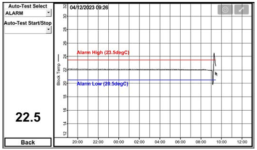
Alarm Auto Test
In most scenarios, the Alarm Auto Test will be the preferred testing option.
How to Use:
-
Use the top drop-down menu to select either:
-
Alarm Test, or
-
Calibration Test
-
-
Once the desired test is selected, use the Start/Stop drop-down menu to begin or end the procedure.
What the Alarm Test Does:
-
Step 1: Cools the aluminium block to 20°C and holds for 5 minutes
-
Step 2: Heats the aluminium block to 24°C and holds for another 5 minutes
-
During this process, the alarms should trigger at:
-
20.5°C (Low Alarm)
-
23.5°C (High Alarm)
-
Total Test Duration: Approximately 15–20 minutes
Calibration Auto Test
The Calibration Auto Test is designed for use by qualified technicians to verify the linear accuracy of the block sensor.
Test Procedure:
-
The test begins by cooling the sensor to 17°C and holding for 15 minutes.
-
The block is then heated to 27°C and held for an additional 15 minutes.
-
A calibrated reference probe should be inserted into the aluminium block to serve as a cross-reference at both temperature setpoints.
This ensures accurate calibration by comparing the STAR X sensor readings with a traceable standard.
Total Test Duration:
Approximately 45–55 minutes

Shut Down Procedure

-
The cabinet is equipped with a battery-backed alarm system. Simply turning off the power will trigger a Power Fail Alarm on the screen.
-
To properly shut down the unit, press and hold the red button on the controller while simultaneously turning off the mains power to the cabinet. This ensures the controller’s power is correctly interrupted and prevents unnecessary alarms.