
Applicable Models:
CLIMATRON-1260
📜 Quick Navigation
Enabling the Temperature Function
Start Up Procedure
- Remove Packaging: Ensure all internal and external packaging materials, including tape, plastic bags, and foam, are removed from the cabinet.
- Locate: Place the cabinet in its designated location, with water and drain connections set up.
- Connect Power: Insert the supplied lead into the IEC socket on the back of the cabinet, then plug the 3-pin connector into a 10A general-purpose outlet.
-
Initial Power-Up: When the STAR-X Touchscreen Controller is powered on for the first time, the following screen will be displayed. At this stage, the cabinet enters Standby Mode, during which only the backup batteries are being charged. All other system functions remain inactive.
-
Factory Settings:
- On the first start-up, the temperature is preset to 25°C, and the humidity function is turned off by default.

- Touch the Thermoline Logo and the “Login” window will appear.

Using the drop-down menu select “User1”.
-
The default login credentials are:
-
User Name: User 1
-
Passcode: 1111
-
Then touch the Login Button. If successful, the message “Login Success” will be displayed.

- Now Touch the screen anywhere outside of the Login Window. Or Close the Login Window and then touch the screen again. The following window will be displayed:

Turning the Cabinet On
To power on the cabinet:
-
Press and hold the “Press & Hold to Turn Cabinet On” button on the touchscreen.
-
A Time-Out icon will appear while the button is being held.
-
Continue holding until the Time-Out completes and a tick icon is displayed.
-
Release the button once the tick appears.
After the cabinet is successfully turned on, the air circulating fans will begin operation.

Star-X Controller Guide

Main Screen Overview
The Main Screen provides a real-time overview of system status and control settings. Below is a description of each element:
-
Set Value (Grey):
Displays the current setpoint that the controller will use once the function is activated.
To adjust: tap the value (for Temperature, Humidity, Light, or CO₂) and a numeric keypad will appear. Enter the new value and press Enter. The cabinet will begin controlling to the new setpoint. -
Set Value (Green):
Indicates that the Programmer is operational and controlling this function. These values cannot be edited directly. Setpoints are managed through the programmed schedule.
See Programmer Set-Up for more information. -
Actual Value (Grey):
Displays the live reading from inside the cabinet for the associated function. -
Actual Value (Red):
Indicates the current value is in alarm condition (e.g., out of tolerance).
Tap the red alarm bell icon to open the Alarm/Events screen, where you can acknowledge the alarm and mute the buzzer.
See Alarm Set-Up for more information. -
Control:
Shows whether the associated control function is On (green) or Off (red).
If a function is Off (red), the system will not control to the setpoint—even if one is entered. This is usually indicated by both Heat OP and Cool OP showing 0.0. -
Heat OP:
A read-only display showing the heating output required to maintain the setpoint.
Displayed as a percentage (0–100%). -
Cool OP:
A read-only display showing the cooling output required to maintain the setpoint.
Displayed as a percentage (0–100%). -
Power Loss Indicator:
Displays a red alarm bell and sounds a buzzer in the event of a power failure.
The STAR-X touchscreen remains powered for approximately 16 hours via backup batteries. -
Cabinet Status:
Indicates whether the cabinet is On or Off.
Use the “Press and Hold to Turn Cabinet On” button to switch the cabinet on.
To perform a full shutdown, first turn the cabinet off using this button before disconnecting from the power outlet.
If the cabinet is still on when power is lost, the Power Loss Alarm will trigger. -
Alarm Bell (Grey):
Indicates that the alarm system is enabled and monitoring.
See Alarm Set-Up for details. -
Alarm Bell (Red):
Indicates an active alarm condition.
Tap the red bell icon to open the Alarm/Events screen, where the operator can acknowledge the alarm and permanently mute the buzzer.
Settings

To access system settings, touch the “Settings” button on the Main Screen. This will open the Settings Screen.
From the Settings Screen:
-
Press the “Main Screen” button to return to the Main Screen.
-
Touch the Thermoline logo to access the Login Screen.

Settings Screen Functions
The Settings Screen provides access to various system features and configuration menus. Below is a summary of each option:
-
Contact Us:
Displays Thermoline's contact details, including phone number, email, and website. -
Trend Screens:
Opens the Trend Screen for Temperature, Humidity, Light, and CO₂.
See Trend Screen Instructions. -
Data Log:
Displays logged trend data in table format and allows the user to download data to a USB-A memory device.
See Data Log Instructions. -
Alarm/Event Log:
Shows a history of active and past alarms and events.
Operators can acknowledge alarms directly from this screen.
See Alarm/Events Instructions. -
Alarm Settings:
A login-protected screen that allows the operator to enable or disable alarms for Temperature, Humidity, Light, and CO₂.
See Alarm Set-Up. -
Programmer:
A login-protected screen for managing control programs. Operators can create, edit, run, reset, hold, or advance a program.
See Programmer Set-Up. -
System:
A login-protected screen for system configuration. Allows the operator to:
– Set the time and date
– Configure network settings
– Enable or disable daylight savings
– Adjust screensaver and backlight timeouts
– Delete alarm/event logs and stored data
See System Set-Up. -
Calibration:
A login-protected screen for performing one-point calibration adjustments for Temperature, Humidity, Light, and CO₂.
See Calibration Set-Up. -
User Accounts:
A login-protected screen for managing user access.
Operators can create user accounts, assign unique passcodes, and define access privileges.⚠️ Note: Passcodes are not recoverable. If lost or changed, they cannot be retrieved.
See User Accounts Set-Up.
-
Service:
A restricted, login-protected screen for Thermoline and accredited service personnel only.
Enabling the Temperature Function
Upon initial power-up, all control functions are disabled by default. The Temperature function must be activated before any other functions become available.
To enable the Temperature function:
-
Press and hold the “Press & Hold to Turn Temp On” button on the touchscreen.
-
A Time-Out icon will appear while holding the button.
-
Continue holding until the Time-Out completes and a tick icon is displayed.
-
Release the button once the tick appears.
Once the Temperature function is 'On', additional control features become accessible. The Temperature function cannot be disabled once turned On. All other functions can be enabled or disabled individually by pressing and holding the corresponding function button.

Adjusting the Set Value
To change a set value:
-
Tap the displayed value you wish to adjust.
-
A numeric keypad will appear on the screen.
-
Enter the desired value using the keypad.
-
Confirm the entry to save the new setting.
Once the desired Function is turned On, the Heat-OP and/or the Cool-OP will automatically adjust to control the Set Value.

Alarms

When an alarm is active, the following indicators will appear on the Main Screen:
-
The Actual value will be displayed in red.
-
The Alarm Bell icon will turn red.
-
An audible buzzer will sound.
To silence the buzzer:
-
Press the Red Alarm Bell icon.
-
You will be taken directly to the Alarm/Events screen.
-
From this screen, you can acknowledge the alarm and permanently mute the buzzer.
Alarm Settings


The Alarm Settings screen is a passcode-protected page. You may be required to log in before accessing this screen.
This screen allows the operator to enable or disable alarms for the following functions:
-
Temperature
-
Humidity
-
Light
-
CO₂
To enable an alarm
-
From the Alarm Settings screen, select the desired function:
Temperature, Humidity, Light, or CO₂. -
Press and hold the corresponding “Alarm Access” button.
-
A Time-Out icon will appear while the button is being held.
-
Continue holding until the Time-Out completes and a tick icon is displayed.
-
Release the button once the tick appears.

When accessing an alarm setting, a drop-down menu will appear.
Use this drop-down menu to turn the alarm ON or OFF for the selected function.

After selecting an option from the drop-down menu, a confirmation pop-up window will appear.
-
Press OK to confirm and apply the change.
-
Press Cancel to discard the change.
⏳ Note: The operator has 10 seconds to confirm.
If no action is taken within this time, the change will be automatically cancelled and must be repeated.
The selected alarm will now be enabled.
Exiting Alarm Set-Up

After confirming any changes:
-
Press and hold the “Exit Alarm Set-Up” button.
-
A Time-Out icon will appear while holding.
-
Continue holding until the icon completes and displays a tick, then release the button.
Once the “Exit Alarm Set-Up” button disappears:
-
The “Settings” button will reappear.
-
Press the “Settings” button to return to the Settings Screen.
If multiple Alarm Access buttons were used, you may need to repeat this process until the Settings button becomes available.
⚠️ Important: After exiting, return to the Main Menu and turn the required functions back ON, as control functions are disabled during alarm changes.
Important Notes:
-
If alarms are required for your process, ensure they are enabled or disabled before operating the cabinet.
-
During alarm configuration, the associated control function is automatically turned off.
-
Alarms cannot be modified while a Program is running. You must first reset the Program before you can access and adjust alarm settings.
-
Once an alarm is enabled, its tolerance settings can be configured in the Program Screen.
- Remember: the associated control function will be turned off during this process and must be manually turned back on from the Main Screen.
Trend Screens


The Trend Screens provide a visual representation of the cabinet’s performance over time. This data mirrors what is available in the Data Log screen and offers real-time insight into system operation.
Key Features:
-
Trend Selection:
The operator can select between the following trend views:
– Temperature Trend
– Humidity Trend
– Light Trend
– CO₂ Trend -
Monthly Data Files:
A new data file is automatically created at the beginning of each month.
The touchscreen can store up to 12 months of trend data. -
Data Recording Interval:
Data is recorded at 1-minute intervals, with each entry date and time stamped. -
File Selection:
Use the “Cog” icon to select which month’s data file you wish to view.
Each trend screen displays data from only one file at a time, as selected in the settings. -
Adjusting Time Scale:
Use the “Arrow” icons to increase or decrease the time span or zoom level of the trend view. -
Date and Time Display:
Each trend screen includes a current date and time display, helping the operator verify that the correct data file is being viewed.

Interpreting Trend Graphs
The Trend Graph provides real-time and historical performance data for Temperature, Humidity, Light, and CO₂ functions.
Graph Indicators:
-
Green Trend Line – Represents the Set/Target Value.
-
Red Trend Line – Represents the Actual Measured Value inside the cabinet.
-
Green Border – Indicates that a Program is currently running.
See Program Set-Up for more information.
Navigating the Trend Graph: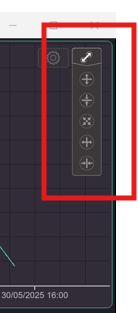
-
Use the “Arrow” icons to:
– Increase or decrease the time scale, allowing you to zoom in or out on the timeline.
– Adjust the function scale to better view small or large variations in data. -
Touch and drag anywhere on the trend graph area left or right to scroll to a specific point in time.
Trend Display Settings
To access the file selection and display options:
-
Press the “Cog” icon on the Trend Screen.
This will open the Trend Settings Menu.

From this menu, the operator can:
-
Select a monthly data file to view.
-
Change the active trend (e.g., Temperature, Humidity, Light, or CO₂).
-
Enable or disable the scale range shown on the left-hand side of the chart.
⚠️ Important: After making any changes, press “Done” to save and apply the new settings.
Channel Visibility

Within the Trend Settings Menu, the Channel Visibility option allows the operator to:
-
Toggle On or Off the display of:
– Set Value (green line)
– Actual Value (red line)
⚠️ Note: At least one channel must remain active; both channels cannot be turned off simultaneously.

The operator can select which channel is required to be viewed. Both Channels cannot be turned off.

The operator can select whether the scale range is on and/or off.
Data Log

The Data Log Screen allows the operator to view and download performance data from the cabinet.
Downloading Data to USB:
-
Insert a USB memory device into the USB slot located on the side of the cabinet.
-
A green USB icon will appear in the bottom right corner of the Data Log screen.
-
Press the green USB icon to begin the data download.
-
The USB icon will change to red, and a message will display:
“Data Backup in Progress. Do Not Remove USB.” -
It is critical to wait until this message disappears and the icon returns to green before removing the USB.
-
⚠️ Do not remove the USB device during transfer. Doing so may corrupt the data.
📁 All available data files (up to 12 months) will be downloaded during this process.
Temporary Lockout of Settings Button:
-
While a USB memory device is inserted, the “Settings” button is disabled.
-
Once the USB device is removed, the button will be re-enabled, allowing the operator to return to the Settings screen.
Viewing Data Logs:
-
Use the “Cog” icon to select the monthly data file you wish to view.
-
The data menu can be scrolled up or down by touch to browse historical data records.

Data Menu without USB memory stick present.

Data Menu showing the green USB icon. Touch the icon the download the data.

The operator can select the monthly files to view.
Alarm/Events Log


The Alarm/Events Log records both alarms and events associated with the cabinet’s operation. This log helps operators monitor system status, review historical issues, and maintain compliance or traceability.
What is Recorded:
-
Events:
The log captures standard operations such as:
– Cabinet turned On/Off
– Temperature, Humidity, Light, and CO₂ functions turned On/Off -
Alarms:
Includes alarm conditions such as:
– Power loss
– Out-of-tolerance conditions for Temperature, Humidity, Light, and CO₂
⚠️ Note: Alarms are only recorded if they have been previously enabled in the Alarm Settings.
Alarm Notifications:
-
Audible alert: A buzzer will sound when an alarm is triggered.
-
Visual alert: The Alarm Bell icon will appear in red on the screen.
-
To silence the buzzer:
-
Locate the active alarm entry in the Alarm/Events table.
-
Touch and acknowledge the alarm entry.
-
The audible alarm will be silenced, but the visual indicator will remain until the alarm condition is resolved.
-
Entry Details:
Each alarm or event entry in the log includes the following time stamps and data:
-
Trigger Date – The date the alarm or event was triggered.
-
Trigger Time – The exact time the alarm or event was triggered.
-
Recovered Time – The time at which the alarm or event condition was resolved.
-
Acknowledge Time – The time the operator manually acknowledged the entry.
-
Message – A description of the alarm or event.
-
Category – Identifies whether the entry is an Alarm or an Event.
Additional Notes:
-
On initial startup, the Alarm/Events Log will display entries indicating that all functions are Off.
-
You may also see reminders such as “Water Filter Reminder”, which is recorded as an event.

By touching an entry in the Alarm/Events Log, the Acknowledge Time is recorded and added to the log.
In the example above, both the “Logged Data Deleted” and “Alarm/Events Deleted” entries have been acknowledged, as indicated by their respective time stamps.

When an Alarm and/or Event is selected, the entry will display with white text.
-
If the condition has not recovered, the entry will appear in red text.
-
Once the condition has recovered, the entry will change to green text.
Description of Alarms and Events
The Alarm & Events feature logs operational activity and alarm conditions, useful for diagnostics and monitoring. Below is a summary of each entry type:
Logged Data Deleted: Indicates when trend data was deleted via the “System” screen.Alarm/Events Deleted: Indicates when the alarm/events log was deleted via the “System” screen.
Program Reset / Run: Logs when a program is reset (default on startup) and when it is started in Run Mode.
[Temp / Humid / Light / CO₂] Alarm Enabled/Disabled: Indicates when an alarm for a function is enabled or disabled. Enabling one will log the disable time as the recovery time, and vice versa.
Cabinet On/Off: Indicates when the cabinet power was turned on or off.
[Temp / Humid / Light / CO₂] On/Off: Logs when each function was turned on or off.
– Note: Temp Off only occurs on full power down. Once turned on, it must remain active for other functions to operate.
Water Filter Reminder: Occurs every 6 months (June and December). Logged when the filter change is acknowledged on the Main Screen.
[Temp / Humid / Light / CO₂] Alarm: Indicates an out-of-tolerance condition for each function. Triggers an audible and visual alarm (red Actual Value and red Alarm Bell). Audible alarm is silenced once acknowledged; visual remains until recovered.
Power Loss Alarm: Triggered during a power failure. Triggers an audible buzzer and red Alarm Bell. Remains active until power returns or the backup battery depletes.
Programmer

The Programmer screen is passcode protected and may require the operator to log in to gain access.
The STAR-X controller includes:
-
8 individual programs
-
Up to 32 segments per program
Each program can be linked to another, allowing for the creation of extended sequences of up to 256 segments.
The Programmer is typically used to:
-
Create diurnal cycles (e.g., day/night simulation)
-
Configure cycles required for compliance with specific standards or protocols
Programmer – Reset Mode

When the program is in Reset Mode, the initial Programmer screen functions as an information screen only. In this state, the following options are available:
-
“Press and Hold to Run Program” button – Used to start the loaded program
-
“Program Number Loaded” – Displays the currently loaded program
-
“Program Edit” button – Opens the editing interface for the loaded program
All other controls and program functions remain inaccessible until the program is running.
Programmer – Run Mode

When the program is in Run Mode, the first Programmer screen displays real-time information about the running program, including:
-
Current Program Number
-
Total Program Time Remaining
-
Current Segment Time Remaining
-
Current Segment Number
-
Current Repeat Count (if used)
Note: While a program is running, the operator cannot edit the program or change the loaded program number.
Additional Controls Available in Run Mode:
-
Advance Segment:
Skips forward to the next segment in the active program. -
Hold Program:
Pauses the program at its current segment. -
Restart Program:
Resumes the program after putting it in Hold mode.
Program Editing – Segments 0–7

After pressing the “Program Edit” button, the screen will display:
-
Segments 0 to 7
-
Alarm values
-
Additional program parameters associated with each segment
From this screen, the operator can configure and adjust the individual settings for each segment, including temperature, humidity, lighting, CO₂, duration, and alarms.
Viewing Additional Segments

If the program contains more than 8 segments, the “Segments 8–15” button will become active.
-
Pressing this button will navigate to the next screen, displaying Segments 8 to 15.
-
Continue pressing the corresponding segment range buttons (e.g., “16–23”, “24–31”) to view and edit further segments as needed.
Segments 16–23
If the program includes more than 16 segments, the “Segments 16–23” button will become active.
-
Pressing this button will navigate to the screen displaying Segments 16 to 23.
-
These segments can be viewed and edited just like previous segments.
Segments 24–31
For programs containing more than 24 segments, the “Segments 24–31” button will become active.
-
Press this button to access and edit Segments 24 to 31.
-
Use the available controls to configure values as needed for each segment.
Programmer Information
Below is a description of each parameter related to the Programmer and its operation:
Edit Program Number:
Drop-down menu used to select the program number (0–7) for editing and operation. Each program is independently configurable. Changing the program number updates all displayed parameters accordingly. This is also referred to as the Program Loaded.
Segments Required:
Each program can include up to 31 segments. Select the number of segments needed to suit the intended cycle.
Example: A simple diurnal cycle may use just 6 segments.
Program Repeats:
Specifies how many times the program should run, up to 100 times (initial run + 99 repeats).
If more than 100 repetitions are required, use the Program Link function.
Program Link:
Allows linking the current program to another program number.
-
No Link: Program ends and resets to Fixed Set-Point (FSP) Mode.
-
Link to same program: Program will loop continuously.
-
Link to another program number: Chains programs together to extend total segment count or create complex cycles.
Temperature / Humidity / Light / CO₂:
Set the desired target value for each function per segment.
Time:
Specify the duration of each segment in Hours and Minutes.
Alarm Hi / Alarm Lo:
If enabled, these values define the deviation limits from the segment’s setpoint that will trigger an alarm:
-
Example: If set to 2.0°C, an alarm will trigger when the actual value is 2.0°C above (Hi) or below (Lo) the setpoint.
-
A 15-minute delay is built in to prevent nuisance alarms (e.g., during door openings).
-
It is recommended not to set alarm values less than 1.0°C, to account for normal cabinet control accuracy.
🔔 Note on Alarm Values:
Alarm values are linked to the currently loaded program, even if the programmer is in Reset Mode.
If alarms are enabled during Reset, they will still trigger based on the values stored in that loaded program.
Program Example – 24-Hour Diurnal Cycle

The following is an example of a 24-hour diurnal cycle, alternating between Day and Night conditions, with:
-
Day Temperature: 40.0 °C
-
Night Temperature: 10.0 °C

Program Sequence:
-
Segment 1:
Start from 25.0 °C, 60% RH, and 0 µmol.
Ramp over 5 hours to reach 40.0 °C, 40% RH, and 100 µmol. (Day) -
Segment 2:
Hold at these Day conditions for 2 hours. (Day) -
Segment 3:
Ramp down over 5 hours to 25.0 °C, 60% RH, and 0 µmol. (Day) -
Segment 4:
Continue ramping down to 10.0 °C, 80% RH, maintaining 0 µmol. (Night) -
Segment 5:
Hold at Night conditions for 2 hours. (Night) -
Segment 6:
Ramp up over 5 hours to return to 25.0 °C, 60% RH, and 0 µmol. (Night)
The program will then repeat, maintaining a continuous day/night cycle.
Starting the Program / Diurnal Cycle
To begin running a program:
-
Navigate to the Programmer page.
-
Press and hold the “Press & Hold to Run the Program” button.
-
A Time-Out icon will appear—continue holding until it completes and displays a tick, then release.
The selected program will now begin running according to the loaded segment settings.
Programmer – Not Operational

When the program is not running (i.e., in Reset Mode or stopped):
-
The Program Number Loaded can still be selected or changed using the drop-down menu.
-
The “Program Edit” button remains available, allowing the operator to view and edit segments and settings for the selected program.
This allows program setup or modification to be completed before the program is started.
Programmer – Program Running (Operational)

When a program is operational and running:
-
A green border will appear around the screen, indicating that the program is active.
-
The “Program Number Loaded” drop-down menu is locked and cannot be changed.
-
The “Program Edit” button is hidden to prevent modifications during operation.
To make changes or select a different program, the current program must be reset or placed on hold.
System


The System Screen allows the operator to configure key device settings and manage stored data. The following functions are available:
Network Settings:
-
DHCP (Dynamic Host Configuration Protocol):
Use the drop-down menu to toggle DHCP On or Off.
– When On, the IP address is assigned automatically.
– When Off, the IP address can be set manually.
Screen Timeout:
The screen includes two timeout features:
-
Screensaver Timeout: Activates a screensaver that allows operator login.
-
Backlight Timeout: Turns off the screen backlight to prolong screen life.
– Touching the screen will wake it from either state.
– Setting either timeout to 0 (zero) will disable that function.
Time, Date & Daylight Savings (DST):
-
To adjust the time or date, tap the displayed value and enter the new value.
-
If the touchscreen is connected to a network, time and date will be updated automatically via the network.
-
Daylight Saving Time (DST) is not automatic and must be manually enabled.
– If in a DST region, toggle DST On and configure the Start and End dates to match your local time zone.
Delete Event History:
-
Clears all event and alarm history.
-
Requires pressing and holding the button for 5 seconds to prevent accidental deletion.
Delete Logged Data:
-
Clears all performance log data.
-
Requires pressing and holding the button for 5 seconds to confirm.
Calibration Screen


The Calibration Screen allows the operator to perform one-point adjustments to the Actual Value of monitored parameters.
This function is used to fine-tune sensor readings when minor discrepancies are observed between the displayed value and an external calibrated reference device.

User Accounts

The User Accounts screen allows administrators to manage access to passcode-protected features. From this screen, you can:
-
Change Privileges
-
Change Passcodes
-
Add Users
-
Delete Users
⚠️ Important:
Use caution when modifying privileges, passcodes, or user accounts. Once confirmed, changes cannot be undone. Incorrect modifications may result in loss of access to the touchscreen.
Default User
On initial supply, the touchscreen includes a single account:
-
User Name: User 1
-
Passcode: 1111
-
Privileges: Full access to all passcode-protected pages
🛑 Before modifying User 1’s privileges, it is recommended to create a new user with full access privileges.
User Account Functions
Change Privileges
-
Press and hold the “Change Privileges” button for 5 seconds.
-
The Privilege Screen will appear.
-
Select the user to modify.
-
Tap each function to toggle access:
– Green: Access enabled
– Red: Access blocked -
Confirm the changes. A message will display “Privilege Change Successful”.
Change Passcode
-
Press and hold the “Change Passcode” button for 5 seconds.
-
Select the user whose passcode needs to be changed.
-
Tap the “New Passcode” window and enter the new passcode.
-
Confirm the change. A message will display “Passcode Change Successful”.
Add User
-
Press and hold the “Add User” button for 5 seconds.
-
Tap the “User Name” window to open the QWERTY keyboard.
-
Enter a new username and press Enter.
-
Tap the “New Passcode” window and enter a passcode.
-
Select the required privileges for the new user.
-
Press “Add Account” and confirm the operation.
A message will display “Account Creation Successful”.
Delete User
-
Press and hold the “Delete User” button for 5 seconds.
-
Use the drop-down menu to select the user to delete.
-
Press the “Delete User” button again and confirm the deletion.
A message will display “User Deletion Successful”.
🚫 Note: The currently logged-in user cannot be deleted. However, if the Auto Logout Time expires and the user is logged out, they may then be deleted.
Auto Logout Time
This setting defines how long a user remains logged in before the system automatically logs them out.
-
Setting to 0 (zero) disables automatic logout—users stay logged in indefinitely.
-
For full access without security, set:
– Auto Logout Time: 0
– Screensaver Timeout: 0
🔓 Disabling both settings effectively removes all access restrictions.
Change Privileges
After selecting “User Accounts” from the Settings screen, the User Management screen is displayed.

To modify user access:
-
Select the desired user from the drop-down list (e.g., User 1).
-
Press and hold the “Change Privileges” button for 5 seconds.
-
The Privilege Management screen will appear.
-
Tap each function to toggle its access:
– Green: Access enabled
– Red: Access blocked -
Once the desired privileges are selected, press “Confirm” to apply the changes.
A confirmation message will indicate “Privilege Change Successful.”

⚠️ Caution:
Take care not to unintentionally lock out all privileges for critical users such as User 1.
As shown in the example above, disabling all access and confirming the change will completely restrict User 1 from all passcode-protected features, which may prevent further access to system settings.
When selecting privileges, the buttons will change to green, indicating that access is enabled for the selected feature.
Once all desired privileges have been selected:
-
Press the “Change Privilege” button.
-
Confirm the operation when prompted.

The selected privileges will then be saved and associated with the currently selected user.
Change Passcode

To change a user’s passcode:
-
Select the user whose passcode you wish to change from the drop-down menu.
-
Press and hold the “Change Passcode” button for 5 seconds.
-
Press OK to confirm the operation and proceed.
-
Tap the “New Passcode” window and enter the desired passcode.
⚠️ Important:
Passcodes are not recoverable. Be sure to select a passcode that the operator will remember.
-
Press the “Change Passcode” button.
-
Press OK to confirm the change.
-
A message will appear indicating “Passcode Change Successful.”
Add New User

To add a new user:
-
Tap the “User Name” window. The QWERTY keyboard will appear

-
Enter the desired username and press Enter.
-
Tap the “New Passcode” window and enter a passcode.
-

⚠️ Note: Passcodes are not recoverable. Choose a passcode that the user will remember.
-
Select the privileges for the new user.
– If the Screensaver is active (not disabled in the System screen), ensure the user has access to it. -
Press the “Add Account” button.
-
Press OK to confirm the operation.
-
A confirmation message will display: “Account Creation Successful.”
Delete User Account

To delete an existing user:
-
Select the “User Name” from the drop-down menu.
🚫 Note: The currently logged-in user cannot be deleted.
⚠️ Deleted user accounts cannot be recovered.
-
Press OK to confirm the selection.
-
Press the “Delete Account” button.
-
Press OK again to confirm the deletion.
-
A confirmation message will display: “User Deletion Successful.”

Water Filter Reminder

In the months of March and September, a Water Filter Reminder will appear on the display. This reminder is shown on both the:
-
Screensaver Screen
-
Main Menu Screen
An Event entry is also recorded in the Alarm/Events Log.
To Clear the Reminder:
-
Log in to the Main Menu.
-
Press and hold the Water Filter Reminder message.
-
A countdown timer will appear—continue holding until it completes and the reminder is cleared.
🔄 The reminder will reappear every 3 months (March, June, September, December) unless disabled.
Shut Down Procedure
-
Power Off: Turning off the mains power will trigger a power fail alarm due to the battery-backed alarm system.
-
Controller Shutdown: Press and hold the red button while switching off the main power to power down the controller fully.